⚡ Cable Termination Failure During Grid Energization – Field Case Study from a 4 MW PV Plant
🔧 Introduction
In large-scale photovoltaic (PV) plants, the commissioning phase is one of the most critical stages of the entire project lifecycle.
Even when all systems are fully installed and tested, unexpected failures can occur during grid energization due to mechanical stress, poor cable routing, or hidden installation defects.
This case study describes a real incident that occurred during the energization of a 4 MW PV plant with two 2 MW transformer stations, where a cable termination failure caused a severe fault at one of the MV cable heads immediately after grid voltage was applied.
⚡ System Overview
| Parameter | Value |
|---|---|
| PV Plant Capacity | 4 MW |
| Transformer Stations | 2 × 2 MW |
| Grid Connection | Medium Voltage (MV) feeder |
| Cable Type | MV armored power cable |
| Installation Type | Indoor transformer stations / enclosed MV transformer rooms |
The system was fully installed, tested, and ready for grid energization.
💥 Incident Description
During grid energization performed by the utility operator, voltage was applied to the MV line feeding the transformer stations.
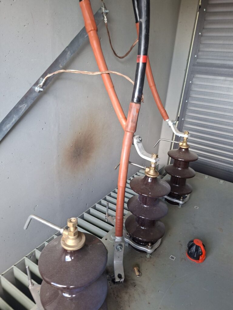
Immediately after energization:
- One cable termination (cable head) failed violently
- The fixing stud (mounting bolt) was mechanically torn off
- The conductor dropped from its support point
- Visible burn marks appeared on the substation wall
The failure caused a temporary outage affecting multiple nearby villages connected to the same feeder.
What is an MV Cable Termination?
A medium voltage cable termination is a critical connection point between the power cable and electrical equipment such as transformers or switchgear.
It ensures:
- Electrical insulation integrity
- Mechanical stress relief
- Safe transfer of high voltage power
Improper installation can lead to partial discharge, overheating, or catastrophic failure during grid energization.
📸 Observed Damage
| Component | Condition |
|---|---|
| Cable termination | Catastrophic failure |
| Fixing stud | Mechanically broken |
| Conductor position | Displaced / unsupported |
| Wall surface | Burn marks observed |
| System status | Immediate shutdown |
🔍 Root Cause Analysis
After on-site inspection and technical investigation, the following root causes were identified:
🔌 1. Excessive Cable Bending During Installation
The MV cable had been bent beyond recommended minimum bending radius during installation.
This created:
- Internal mechanical stress in conductor strands
- Uneven stress distribution at termination point
- Weak mechanical integrity under load
🌪️ 2. Mechanical Stress Amplified by Grid Energization
During energization:
- Sudden voltage application created electromagnetic forces
- Thermal expansion started immediately under load
- Mechanical vibration occurred in unsupported cable section
This triggered failure at the weakest mechanical point.
⚙️ 3. Insufficient Mechanical Fixing Strength
The termination support structure was not strong enough to withstand:
- Cable weight + tension
- Dynamic electromagnetic forces during energization
- Pre-existing stress from installation bending
📊 Failure Mechanism Summary
| Stage | Event |
|---|---|
| Installation | Excessive cable bending |
| Pre-energization | Hidden mechanical stress present |
| Grid energization | Sudden electrical and mechanical load |
| Immediate reaction | Mechanical failure at termination point |
| Result | Cable head detachment and fault |
🧪 Post-Incident Requirements
After repairing the damaged termination, the utility operator required strict verification before re-energization.
The following tests were performed:
- 🔬 Insulation resistance measurement
- ⚡ High-voltage withstand (HiPot) testing
- 📏 Cable integrity verification
- 🧪 Laboratory confirmation of compliance
Only after receiving certified test reports confirming compliance with standards, the grid operator approved reconnection.
📋 Compliance Requirement Table
| Test | Purpose |
|---|---|
| Insulation Resistance Test | Detect insulation damage |
| HiPot Test | Verify dielectric strength |
| Continuity Test | Ensure conductor integrity |
| Mechanical Inspection | Confirm proper termination |
⚠️ Key Technical Lessons
🔴 1. Cable bending radius is critical
Even if the system passes initial tests, mechanical stress can remain hidden until energization.
🔴 2. MV terminations are highly sensitive
Cable heads must be installed with strict adherence to:
- Manufacturer torque values
- Mechanical support requirements
- Proper alignment
🔴 3. Grid energization is a high-stress event
Even in “idle” state systems, energization introduces:
- Electrical surge stress
- Mechanical vibration
- Thermal expansion effects
🔴 4. Post-fault testing is mandatory
After any MV failure:
- Field repair is not sufficient alone
- Laboratory validation is required
- Utility approval depends on certified results
📉 Impact of the Incident
- Temporary grid outage affecting multiple settlements
- Delay in commissioning of 4 MW PV plant
- Additional inspection and testing costs
- Mandatory compliance verification process
🧠 Conclusion
This case demonstrates that even fully completed PV installations can experience severe failures during the final energization phase if mechanical installation quality is not strictly controlled.
The root cause was not electrical design failure, but mechanical stress introduced during cable installation, which only manifested under real grid conditions.
Proper cable handling, strict bending radius control, and robust termination support design are essential to ensure long-term reliability of medium voltage PV connections.
🔗 Related Articles
Huawei Error 2032 – Grid Fault / Grid Abnormal: Causes, Diagnosis & Fix